Bí quyết để giữ cho Mac mini cổ đại hoạt động mãi mãi
Th8
Làm thế nào để giữ cho một chiếc Mac mini cũ hoạt động
Những chiếc Mac cũ vẫn có nhiều điểm nổi bật trong việc sử dụng và chức năng. Dưới đây là cách để giữ cho Mac mini cũ của bạn hoạt động như mới. Trong bài viết này, chúng ta sẽ tìm hiểu về cách trang bị lại hai mẫu Mac mini đầu tiên từ Apple: Mẫu PowerPC G4/1.42 GHz và Mẫu Core Duo 1.66 GHz dựa trên bộ xử lý Intel. Cả hai máy đều là những mẫu mini polycarbonate đầu tiên mà Apple đã sản xuất. Trên thực tế, mẫu 1.25GHz và mẫu 1.42GHz đều được giới thiệu vào ngày 11 tháng 1 năm 2005. Máy 1.42 GHz là chiếc Mac mini thứ hai từng được sản xuất. Mẫu 1.42 GHz còn cung cấp tùy chọn cổng modem. Mẫu 1.66GHz được giới thiệu vào ngày 28 tháng 2 năm 2006, và thực chất là như những mẫu khác chỉ có sự cải tiến về tốc độ và một số cổng kết nối phía sau. Đây là mẫu Mac mini thứ sáu từng được giới thiệu. Bạn có thể xem thông số kỹ thuật chi tiết về mỗi mẫu Mac mini từ trang EveryMac. Mặc dù bài viết này tập trung chủ yếu vào mẫu 1.66GHz, nhưng 14 mẫu Mac mini đầu tiên rất tương tự, nên hướng dẫn này cũng áp dụng cho tất cả các mẫu đó. Bắt đầu trang bị Đầu tiên, chúng tôi cần lưu ý rằng những chiếc máy này rất mỏng manh bên trong và chứa nhiều bộ phận nhỏ và dễ vỡ. Vì đã gần hai thập kỷ trôi qua, nhựa chúng có thể bị mẻ nứt, và việc tháo rời chúng luôn mang theo nguy cơ hư hỏng các bộ phận, vì vậy hãy tiếp tục cực kỳ cẩn thận. Bạn sẽ cần những công cụ sau để tháo các chiếc Mac mini này: Một cây vít có đầu phíp magnetize kích thước vừa Một cây vít nhỏ có đầu phíp magnetize, hoặc một cây vít nhỏ có cán kim hoặc cây sợi đàn ông nhỏ Dụng cụ nhựa phẳng nhỏ hoặc kim loại Compressed air hoặc máy nén khí Một cây đèn pin sáng Đèn chiếu sáng phòng sáng tương đương Tùy chọn là một kính phóng đại nhỏ hoặc một lưỡi phóng đại kim hoặc lưỡi người đánh bóng Kapton Một viên pin CR2032 thay thế Mắt sắc và bàn tay vững Step 1: Mở Mac mini của bạn Để mở Mac mini, đặt nó mặt xuống trên một bề mặt phẳng với một tấm vải mỏng dưới đáy máy để tránh làm hỏng. Xoay nó sao cho phần trước của máy đối diện bạn. Sử dụng cây dụng cụ cán hồi 4,5 inch, cẩn thận đèn cụ vào thành máy ở phía bên phải giữa vỏ kim loại bên ngoài và viền nhựa trắng. Với một động tác, nhấn xuống vào tay cầm của dụng cụ và sang phải, áp dụng lực từ trên xuống dưới. Viền phải của máy sẽ mở ra. Tiếp theo, lặp lại quy trình tương tự nhưng trên mặt trước máy, sử dụng một động tác nhanh duy nhất để mở ra. Cuối cùng, đặt dụng cụ vào phía trái cuối máy ở góc sau và trượt nó sang phía trước để vừa vặn vào vỏ máy. Bước này khó khăn nhất vì với vỏ máy bị nghiêng, có rất nhiều ma sát và ít không gian ở phía trái. Hãy cẩn thận như những bước khác, cho đến khi phần đáy máy được tách ra khỏi nắp kim loại phía trên. Chưa cần hoàn toàn tách nó ra – chỉ cần nhấc lên cho đến khi hai nửa tách rời nhau, sau đó gỡ bỏ dụng cụ. Bây giờ lật máy qua lại và cầm nó bằng cả hai tay, sử dụng ngón cái ở phía sau máy ở nửa dưới, nhấn mạnh để hoàn toàn giải phóng nó ra khỏi nắp trên. Bạn có thể nghe thấy một âm thanh nhỏ khi phần trên bị bung ra. Đặt nó sang một bên tạm thời. Bên trong, như được hiển thị trong bức ảnh dưới đây, bạn sẽ nhận thấy một ổ đĩa DVD ở trên cùng, một ăng-ten AirPort ở phía sau bên phải, một ăng-ten/ cảm biến Bluetooth tùy chọn ở phía trái, một loa và viên pin button-cell ở mặt trước. Bộ phận thu vi điều khiển hồng ngoại cũng nằm ở phía bên phải mặt trước, với dây cáp được kết nối với bo mạch chủ ở phía dưới đáy máy. Trên ổ đĩa DVD, bạn sẽ nhận thấy 4 ốc vít phíp nhỏ, và hai ốc vít phíp lớn theo cạnh trái. Bốn ốc vít nhỏ giữ ổ đĩa DVD vào bộ khay nhựa trung tâm chính, và hai ốc vít lớn giúp giữ ổ cứng nội bộ 2.5-inch vào mặt dưới của khay. Có 4 ốc vít nhỏ ở mỗi góc của khay chính, và chúng dễ bị lỡ nếu bạn không nhìn kỹ. Hai cái trong số đó ẩn trong các cấu trúc nhỏ ở hai góc bên phải, và một cái nhỏ thứ ba có thể nhìn thấy ở góc bên trái của khay. Viên vít thứ tư, và lớn hơn một chút, cũng ẩn trong một cái cấu trúc nhỏ ở góc sau bên trái của máy. Chú ý viên vít này vì nó rất quan trọng về sau. Ở phía sau của máy là một bo mạch in mini (PCB) nhỏ gắn vào phía sau của ổ đĩa DVD, cũng với hai ốc vít nhỏ. Có một dây cáp màn dẫn phẳng nhỏ gắn vào một đầu nối nhỏ ở giữa PCB. Hãy chú ý rằng dây ăng-ten AirPort đi qua giữa bên trái của PCB và lỗ thoát khí nhựa phía sau. Bước 2: Tháo lỏng ăng-ten AirPort Dùng hai ngón tay, rất cẩn thận và nhẹ nhàng kẹp chặt hai kẹp nhựa nhỏ dưới mô-đun ăng-ten AirPort và nâng lên. Nó sẽ tự do khỏi trụ nó đang đặt. Có cả một lò xo bên dưới nên hãy gỡ bỏ và để nó một bên. Không cần áp lực quá mạnh để bóp hai kẹp nhựa để giải phóng ăng-ten, vì vậy đừng áp lực quá mạnh. Hãy nhớ rằng nhựa là dễ vỡ. Mô-đun ăng-
Old Macs still have a lot to offer in terms of usage and functionality. Here’s how to keep your old Mac minis running like new.
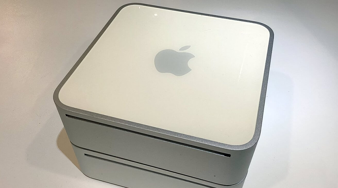
In this article we’ll take a look at refurbishing two of the earliest Mac mini models from Apple: The PowerPC G4/1.42 GHz model and the Intel-based Core Duo 1.66 GHz. Both machines are some of the earliest “polycarbonate” mini models Apple made.
In fact, the 1.25GHz and the 1.42GHz models were both introduced on January 11th, 2005. The 1.42 GHz model was the second Mac mini ever made. The 1.42 GHz model even offered a modem port option:

The 1.66GHz model followed on Feb. 28th, 2006, and was essentially the same except for the speed bump and a few extra ports on the back. It was the sixth Mac mini model. You can view comprehensive specs on every Mac mini ever made at EveryMac.
While this teardown is mostly for the 1.66 GHz model, the first fourteen Mac minis were very similar, so most of this guide applies to all those models as well.
Getting started
First, we should caution you that these machines are very delicate inside and contain numerous tiny and fragile parts. As nearly two decades have passed, their plastics are likely to be brittle, and disassembling them always carries the risk of damage to components, so proceed with caution.
You’ll need the following tools to take one of these Mac minis apart:
- A medium magnetized Phillips-head screwdriver
- A tiny magnetized Phillips-head electronics screwdriver, or jeweler’s screwdriver
- A small flat plastic or metal spudger
- Scissors
- Compressed air or an air compressor
- A bright flashlight
- Bright room lighting
- Optionally a small magnifier or jeweler’s loupe
- Kapton tape
- A CR2032 replacement button-cell battery
- Sharp eyes and a steady hand
Step 1: Open your Mac mini
To open your Mac mini, lay it face down on a flat surface with a thin cloth underneath to prevent damage. Rotate it so the front of the machine is facing you.
Using the 4.5-inch wall spackling tool, carefully wedge the tool into the machine’s case on the right side between the outer metal cover and the white plastic rim. With one motion, press down on the tool’s handle and to the right, applying upward force.
The right edge of the case should come loose.

Next, repeat the process the same way but on the front of the case, using a single quick motion to pry it up.
Finally, work the tool into the case’s left side at the back corner and slide it forward to fit it fully into the case. This step is the hardest because with the case now tilted, there’s a lot of friction and little space on the left side.
Pry up as with the other two sides, until the bottom of the machine comes loose from the top metal cover. Don’t remove it fully yet – just pry until the two halves are separated, then remove the tool.
Now flip the machine over, and holding it with both hands, use your thumbs at the rear of the machine on the bottom half, pressing it fully free from the top cover. You’ll probably hear a slight crunching sound as the top comes off. Set it aside for now.
On the inside, as shown in the photo below, you’ll notice a DVD drive on the top, an AirPort antenna on the back right side, an optional Bluetooth antenna/case sensor on the left side, a speaker, and the button-cell battery on the front. The IR remote’s sensor is also on the front right side, with its cable attached to the front of the motherboard at the bottom of the case.

On the DVD drive, you’ll note 4 tiny Phillips screws, and two larger Phillips screwed along the left side. The four tiny screws hold the DVD drive onto the main central plastic carrier, and the two larger screws help hold the 2.5-inch internal hard drive to the underside of the carrier.
There are 4 tiny screws at each corner of the main carrier, and they’re easy to miss if you don’t look closely. Two of them are hidden down small shafts on the two right-side corners, and a third tiny one is visible on the carrier at the left corner.
The fourth, and slightly larger carrier screw is also hidden in a small shaft on the machine’s rear left corner. Make note of this screw because it will be important later.


At the rear of the machine is a small printed circuit board (PCB) attached to the rear of the DVD drive, also with two tiny screws. There’s also a small flat ribbon cable attached to a tiny connector at the center of the PCB.
Also note that the AirPort antenna’s wire fits between the left side of the PCB and the rear plastic exhaust vent.
Step 2: Loosen the AirPort antenna
Using two fingers, very carefully and slightly pinch the two small plastic clips under the AirPort antenna module and lift up on the module. It will come free from the post it sits on. There’s also a spring under it, so remove that and set it aside.
It doesn’t take much force to squeeze the two plastic clips to free the antenna, so don’t apply too much force. Remember, the plastics are brittle.
The antenna module is made by Tyco and has an Apple part number on the bottom of it should you need to replace it.
Step 3: Loosen the DVD drive screws, ribbon cable, and board
Next, using your tiny screwdriver, remove the four screws on both sides of the DVD drive and set them aside. They’re easy to lose so be careful. Don’t yet remove the two tiny screws on the PCB.

Note that the other end of the ribbon cable is attached to the motherboard at the back of the unit so it has to be freed first before you can remove the main carrier unit from the computer.
Next, using the spudger tool or a very thin hobby knife pry up the tiny plastic connector holding the ribbon cable in place. This connector has two parts: a top and bottom.
Pry one end up carefully, then pry the other end up slowly while pulling up gently and slowly on the ribbon cable. When just enough force is applied, the cable will come free.

One odd thing about this connector is that the small flat top part will come completely off if you apply enough force once the ribbon cable is free. You’d rather avoid that happening, so be very careful and go slowly.
The other odd thing about this connector is once the ribbon cable is re-inserted, the friction on the top part of the connector increases and it’s harder to move. We’ll see this in action when we reassemble the unit below.
Step 4: Remove the main carrier unit from the Mac
Using the spudger or a tiny knife, carefully unplug the IR sensor module’s two-wire connector on the front of the machine, to the right of the button-cell battery. Be very careful as the connector and wires are tiny and fragile.
In this photo, from left to right are: the speaker, case clip, battery, IR sensor connector, IR sensor:

Next, using the tiny screwdriver, remove the four tiny screws located at each corner of the carrier as described above. These screws hold the carrier unit to the bottom of the machine’s case.
Once the screws are free, and holding the unit in both hands, pull up on the carrier unit, and press down on the bottom of the machine with your thumbs.
You’ll feel a slight resistance. That’s the DVD drive’s small PCB which is inserted into the SATA connector on the motherboard underneath.
Continue pressing until you overcome the resistance and the carrier unit comes free of the bottom half. Also be careful of the AirPort antenna wire while you do this as it is connected to an AirPort module just under the PCB.
Set the bottom half of the machine aside for now.

Step 5: Remove the DVD drive
Next remove the two tiny screws from the DVD drive’s PCB board.
Now that all the screws and cable are free, you can remove the DVD drive. It tends to want to come out on the side opposite the two large drive screws on the left side of the machine, so gently press forward and to the right side (left side if facing the machine from the back) to slide the DVD drive both out of the carrier and to detach it from the PCB at the rear.
Set the DVD drive aside for now.
Step 6: Remove the hard drive
Most of the early Mac minis shipped with a 2.5-inch standard hard drive. You’ll probably want to replace the drive with a new 2.5-inch SATA SSD or a larger capacity 2.5-inch hard drive.
Flip the carrier unit over, and peel off the T-shaped foam pad on the bottom of the hard drive. Set it aside.
Next, remove the two large screws on the left side of the carrier, and the two similar large screws from the bottom of the hard drive. Once the screws are free, only the drive’s SATA connector friction holds it to the carrier.

You’ll need to press the drive forward and to the left to free it from the PCB’s connector. You may need to wiggle it slightly to free it.
It’s rather remarkable how Apple sandwiched the drive into the carrier unit.
Step 7: Remove all dust
Now, using compressed air or an air compressor, blast all the dust out of the carrier, the fan unit, the hard drive, DVD drive, and from the bottom half of the computer. The vendor and model number of the fan are printed on the fan’s bottom side so if your fan has failed, you can find a new one online to replace it.

To really clean the fan well, it can be removed by loosening the 3 tiny screws holding it in, but it’s probably not necessary. A few strong blasts of air are enough to remove most dust and dirt.
Also, note that the PCB never comes completely free of the carrier as it has several other wire connectors and is attached to the rear of the carrier with adhesive. There’s no need to remove it unless it’s damaged.
Once the hard drive is removed and all parts are cleaned, reassembly is basically the same steps in reverse.
Step 8: Install a new 2.5-inch drive
Install the new 2.5-inch SSD or hard drive into the carrier in the same way you removed the old one, taking care to be sure its SATA connector is firmly seated on the PCB’s connector.

Re-install all four drive screws, and then press the T-shaped foam strip back into place in the same position you removed it from, but on the new drive.
Step 9: Re-install DVD drive
Slide the DVD drive back into the carrier, with its rear SATA connector attaching to the SATA connector on the front of the PCB. Reinstall the two tiny PCB board screws using the screwdriver.
You can also reinstall the four side screws on the DVD drive now, or do it later. Doing it now makes the carrier unit more stable, and it’s easier than doing it once the carrier is reinstalled, but either way will work.
Here is the fully cleaned and reassembled carrier:

Step 10: Clean and check lower assembly
Before you reinstall the carrier to the bottom of the machine, inspect the motherboard, the AirPort card, its antenna cable, and other parts. In particular check the small round SMD capacitor marked “25V” at the left edge of the motherboard next to the AirPort card.

These capacitors contain electrolytic fluid and are known to leak over time. If you notice any corrosion or discoloration around the capacitor, you should probably replace it using a soldering iron, but that’s beyond the scope of this tutorial.
Also, be aware of any strange smells around the capacitor – the electrolytic fluid inside these components is known to have a somewhat fishy smell, so if you notice any odd odors, that’s the first thing to check.
You’ll also want to check the tiny gold connector at the end of the AirPort antenna cable where it attaches to the AirPort card. These connectors are notorious for coming loose easily and when you go to reinstall the carrier unit to the bottom of the machine, it’s easy to pull the cable off.
It’s odd Apple didn’t secure the connector with a small strip of Kapton tape. If you have any handy, go ahead and apply a small piece over the connector now to secure it to the AirPort card.
Note the carrier’s PCB board socket just behind the AirPort card. When you reassemble the machine, you’ll need to make sure the PCB connector’s edge fits snugly into this socket.
Step 11: Optional – Replace RAM
If you like, you can upgrade the machine’s RAM to a maximum of 2GB. The specs for the RAM are listed on EveryMac, and are shown below:

Both memory DIMMS must be the same type and speed, but size can vary within limits – for example, a 1GB and a 512MB together will work fine – as long as both combined don’t exceed the maximum RAM limit (2GB).
To remove the old DIMMs, press gently on the two small metal clips on each side while pulling up the DIMM and sliding it forward, out of its socket. Be careful as the clips are tiny and can easily break off if too much pressure is applied.
To install new DIMMs, do the reverse: slide each new DIMM into its socket until it clicks, then press down slightly to lock the clips in place.
Step 12: Optional – Replace button-cell battery
Next, using the spudger or small plastic knife, remove the CR2032 button-cell battery from its socket on the front of the lower half of the machine. There are two metal contacts holding it in place, so you may have to wiggle it a bit to remove it.
If you have a voltmeter, test the battery to make sure it can emit 3V DC. If not, replace it with the new one.
If you don’t have a voltmeter, go ahead and replace the battery anyway. Be sure the “+” side faces the front of the machine.
Also note the tiny copper clip just to the left of the battery. This piece actually connects to the bottom of the DVD drive’s metal case, and the inside front of the machine’s top case, creating a connection.
If this connection is broken, the machine won’t work.
The copper clip tends to come off over time as it’s only held on by thin adhesive on the top of the carrier, and the adhesive usually dries out over time. If this is true on your machine, or if the clip falls off, just reattach it with a drop of Loctite or another fast-drying adhesive.
There’s a small peg on the top of the carrier, and a small hole on the back of the copper clip which it fits onto – so it should be easy to line up. Notice it doesn’t make any connection to the carrier itself – only between the DVD drive and top case.
Finally, reconnect the IR receiver’s small two-wire plug onto the motherboard just to the right of the battery.
Step 13: Reinstall the carrier
With the bottom half of the unit facing away from you, lower the carrier down onto the bottom half of the machine, making sure the PCB board’s connectors are lined up, and that the four corner screw holes are lined up.
Also, make sure the AirPort antenna’s cable is positioned between the rear exhaust port and the small PCB attached to the rear of the machine. The cable has to come up through this opening, then to the left in order to reinstall the antenna on the carrier:

Press down gently until the carrier’s PCB locks in place. Reinsert the four corner screws, making sure the largest one is reinstalled in the same position it was removed from.
This is important because the screw creates a ground connection to the top of the motherboard once secured. Without this connection, the machine won’t work.
Don’t over-tighten the screws as it’s easy to strip the threads on both the screws and the bottom case. Apply just enough force to make them snug.
Step 14: Reconnect the PCB ribbon cable
This is perhaps the most difficult and fiddly step of reassembly. You’ll need to reconnect the carrier’s ribbon cable to the rear of the PCB using the small clip on the PCB.
The easiest and best way to do this is to reposition the top half of the connector, snap it on fully, then using the spudger or a hobby knife, pry both corners back up just a bit, but not enough to remove the clip. Do this before you reinsert the cable.
While the clip is in this position, reinstall the ribbon cable into the PCB connector by pressing it gently down into place. Once it snaps into the connector, the top half of the clip will be captive and won’t come off. You can then press each corner of the clip down using your tiny screwdriver.
Once both sides of the clip are secured, the entire connection will be solid and won’t come loose.
It may take a few tries to get the clip in place but with patience, it’s fairly easy. Go slow and don’t apply too much force. If in doubt, remove the ribbon cable and start over.
The final, correct connection is shown below, under the right arrow:

Also note the position of the AirPort antenna cable, just to the left.
Step 15: Reinstall AirPort antenna
Now that the carrier and ribbon cable are secure, reinstall the AirPort antenna onto its post by first reinstalling the spring onto the post, then snapping the antenna board down onto the two small plastic clips on both sides of the post. The antenna will lock into place.
The spring acts as yet another security/electrical feature designed to prevent the machine from working unless the case is assembled: it presses down slightly and makes contact, acting like a switch once the case is closed.
Without the antenna module being pressed down when the case closes, it won’t work.
Here’s the fully reassembled Mac, except for the top case:

Step 16: Reinstall top case
This final step is also difficult to get perfect but can be done with patience.
The main difficulty in reinstalling the top half of the case onto the bottom half is the fact there are both plastic clips all the way around the bottom half on three sides, and there are also small metal clips around the rear panel on the bottom half.
The metal clips also act like a switch and must make contact with the metal inside of the top half of the case.

The initial alignment and closure of the case are fairly easy, but closing it completely requires a fair amount of force, and if everything isn’t lined up perfectly, either the plastic clips can break off, or else the metal clips can slip outside the top half of the case and prevent it from closing completely.
If the latter happens, the case will appear to close, but there will be a small gap around the rear panel where the top half of the case seats against it.
In order to avoid this, flip the top half of the case face down on a surface, with the front facing away from you, then flip the bottom half over and slowly lower it into the top half.
Check the clips on all sides, and the rear, and press down very slowly and gently, but don’t close the case completely.
After the two halves slide together, and the top half has cleared all the plastic clips on all sides, stop, and flip the machine on its front, with the rear panel facing up. Using a flashlight, inspect the alignment of the metal clips all the way around the rear panel.
If any are outside the top half of the case, use your tiny screwdriver to press them down and inside the top half.
You may have to wiggle them a bit to get the alignment perfect. Note that they are slightly curved, and thus act like small springs against the top half of the case on the inside.
You want the clips on the inside, not the outside all the way around the rear panel. What you don’t want is this:

If this happens, you’ll need to walk the top half of the case back off just a bit, press the metal clips in place, then reapply pressure to the bottom.
Once you’re certain all the clips on all sides are in perfect position, and that nothing is protruding, lay the machine top-down on a surface once again, and give the bottom of the case one final even downward push with force. This will seal the case – as if it had never been opened.
There should be no gaps on any sides, anywhere – not even tiny ones. If there are, you’ll need to use the spackling tool to open the case again and start over. Take your time and be careful. Forcing the case closed won’t work unless everything is perfectly aligned.
Step 17: Reinstall Mac OS X
Now that the physical hardware modernization is done, it’s time to install software.
Reconnect the machine to a monitor via DVI or DVI->HDMI using an adapter, and plug in its power brick.
With an appropriate Mac OS X install CD or USB thumb drive ready, power on the machine.
You should hear the customary bong sound and get a grey screen with a flashing folder. This means the machine can’t find an OS on any bootable drive.
Either insert a Mac OS X installer DVD or a USB thumb drive with an installer on it, and the Mac should detect it and boot into the install media.
Once booted, you’ll need to exit the installer to Disk Utility, format the new internal 2.5-inch drive you installed as Mac OS Extended, then quit Disk Utility and head back into the installer.
Once back in the installer, select the internal 2.5-inch drive as the install target and install the OS. It may take some time if you are installing from DVD as the old DVD drives tend to be a bit slower.
The 1.66 GHz mini model can run Mac OS X 10.6 Snow Leopard, and the 1.43 GHz model can run 10.4 Tiger.
Once the installer finishes, click Restart, and after the bong sound, hold down the Mac’s mouse button. This will force-eject the DVD before the machine boots. Or if using a USB installer, be sure to unplug it from the Mac before restarting.
The machine will boot from the internal 2.5-inch drive you installed onto. Once booted to the Finder, open System Preferences, and click the “Startup Disk” icon. Set the internal 2.5-inch drive as the Startup Disk for future booting.
Once connected to a network, you may want to also try to run Software Update but it’s not clear how long Apple supports ancient versions of Mac OS X for on their update servers.
There are also downloadable .pkg installers for the updates, but you’ll need to search Apple’s support site or online to find them.
The last released version of Mac OS X 10.6 was 10.6.8 so if you’re using a model that supports 10.6, you’ll want to update to that version.
And just like that, your newly refurbished Mac mini lives again:

AI